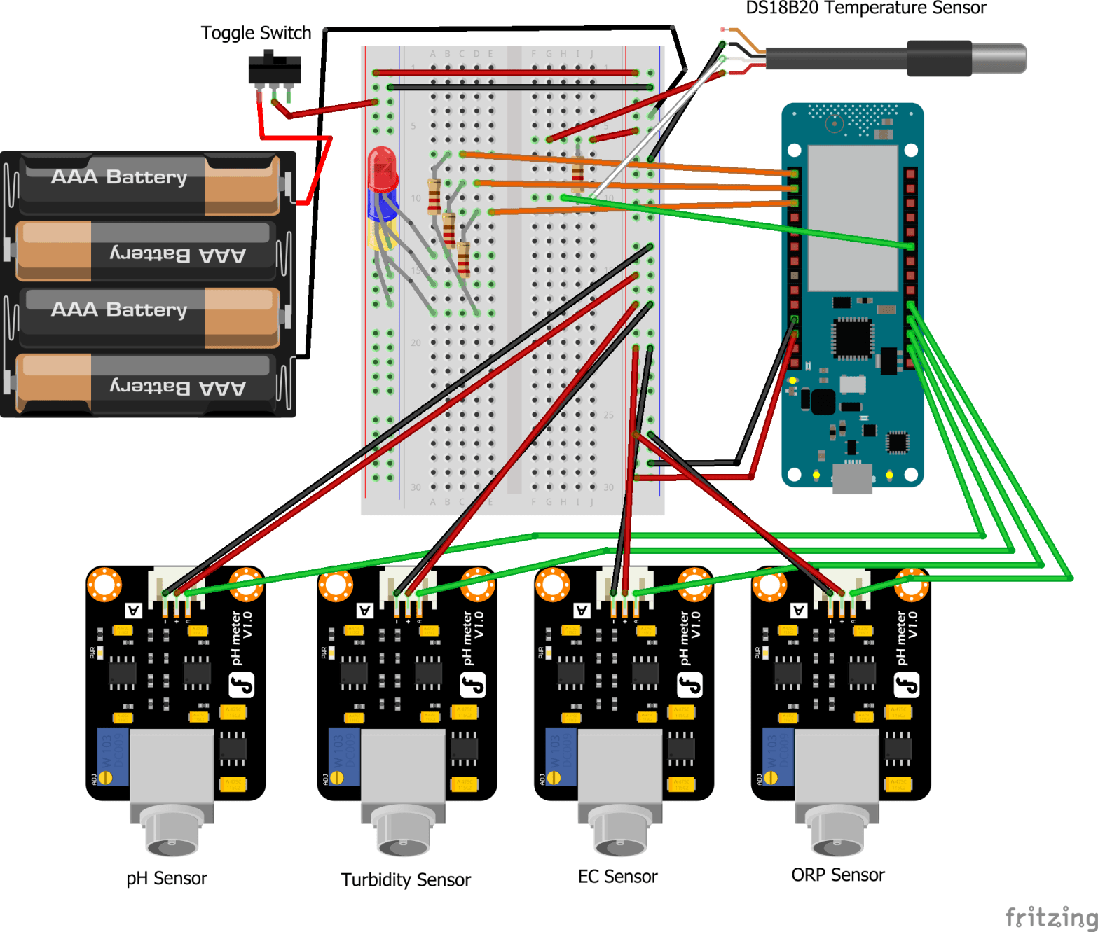
Having finally completed the building and soldering process, here’s a fairly detailed view of the schematics, made with Fritzing [1]:
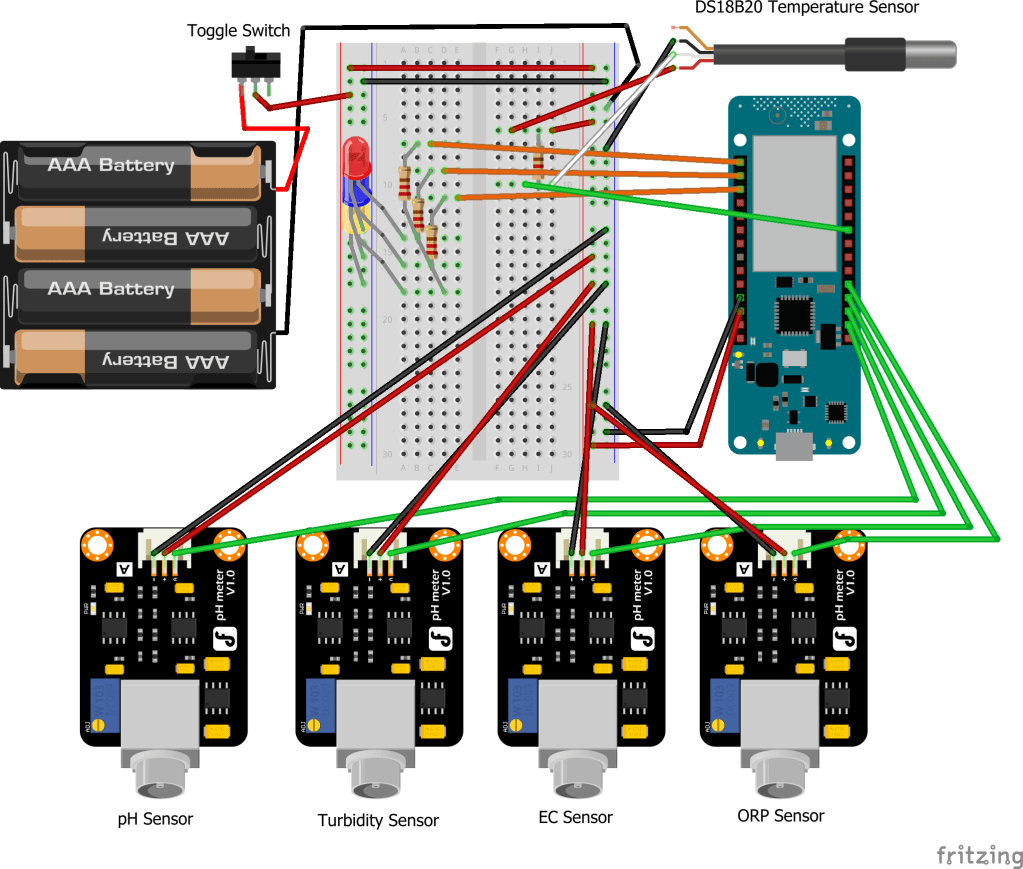
It is worth mentioning that in the prototype, the batteries used are AA batteries, not AAA batteries. Also, I duplicated the pH sensor schematic part because I wasn't able to find the other sensors' schematics online. In reality, the parts look the same. Therefore those who are interested can still grasp the general purpose of this post, which is to show how the different electronic parts are wired together.Throughout the posts, all parts have been covered in detail except for the toggle switch and different colored LEDs. The toggle switch comes in very handy, as it allows the user to take readings without worrying about draining the batteries. Once the readings have been taken, the user can simply shut off the device by flicking the switch to the OFF position. Since the switch is directly connected to the battery, all current is cut off.
As for the LEDs, in a classic finite state machine (FSM) manner, they serve as a way to tell in which state the device is running in. H2OSupport has three states:
- Connecting to the network
- Reading sensor data
- Sending data online
The first state is represented by the red LED. When the device is turned on, the red LED lights up, as the device is trying to connect to the network. If this step fails, all LEDs start blinking and the device needs to be reset (switched off and on).
The second state is represented by the blue LED. Once the device is connected, the red LED turns off, and the blue LED starts blinking for 10 seconds. This 10 second time is given to let the user have enough time to set the device in the water. Once the 10 seconds is up, the blue LED stays on for around 40 seconds, while it takes readings from all of the five sensors.
The final state is represented by the yellow LED. Once the readings have been taken, saved and parsed, the blue LED turns off and the yellow LED turns on. The device is now attempting to send the data online via the connected network. There is no clear way to tell if the data failed to be sent. After rigorous testing, although pretty rare, I can affirm that if this state takes more than a minute to complete, the sending has probably failed.
Once the data is sent, all three LEDs start blinking and the device can be turned off. If the device is left on, the whole cycle will restart, and more readings will be taken and sent.
Sources
[1] Fritzing, Electronics Software Design Tool. [Online]. Available: https://fritzing.org/
